[about]
The STM32F4 MIDIBox is a new open software+hardware project of mine.
It is currently based on an STM 32F407VGT6 micro controller.
An alternative design which uses a TI MSP430G2553 micro (less expensive
but not fast enough for digital signal processing / audio) is under
development.
I designed this box to function as a programmable MIDI controller for
my
Syntracker² audio/MIDI tracker/sequencer.
Since it actually is a quite general purpose device, it can be used with
other MIDI software, as well.
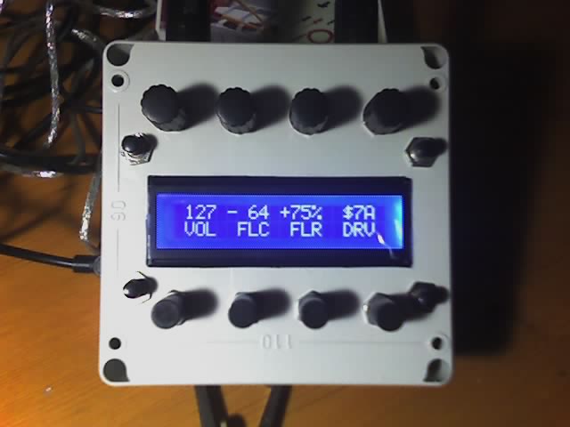
Hardware features:
- 4 pushbutton rotary encoders
- 4 potentiometers
- 4 buttons
- a 20x2 super twisted nematic LC display
- MIDI in and out
- stereo line-out (rev3+)
- USB power / SWD (debug interface)
- (optional) VGA out
Software features:
- 16x pot/rotary multiplexer (virtual pots)
- 20 channel general purpose signal monitor
- full MIDI SysEx programmability
- softsynth / ST² mod replay (WIP)
- step sequencer (WIP)
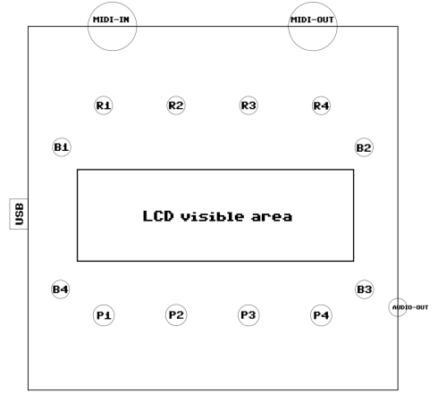
[layout]
MIDI in MIDI out
o o
| |
+---------------------------------------+
| |
| |
| R1 R2 R3 R4 |
| |
| B1 B2 |
| |
| ################################### |
| # # |
USB o--| # <20x2 LCD> # |
| # # |
| ################################### |
| |
| B4 B3 |
| |
| P1 P2 P3 P4 |--o stereo line out
| |
| |
+---------------------------------------+
legend:
R1..4: pushbutton rotaries
P1..4: potentiometers
B1..4: buttons
[usage]
Connect the MIDI and the USB plugs. Upon power-up, the box
displays the firmware build date.
Press B4 to enter the device menu. Here you can adjust the
LCD backlight brightness (B4->press R2->rotate R2), and
get some info about the HW/SW revisions, the box itself (msg),
and see the 20# signal monitor (B4->press R4->press R3).
The firmware is still under construction. Future releases will
allow to switch between different scenes, change the MIDI
config (channel, omni mode, ..), and read/write the configuration
from/to flash memory.
In regular mode, use B1 and B2 to scroll through the virtual pots.
The scrolling speed (default is 4, i.e. paging) can be adjusted
via SysEx.
Keep R1..4 pressed to activate a midi out message lock - moving the
pots will not send MIDI messages any longer until the rotary button
is released (the most recent pot value will then be sent via MIDI).
Alternatively, hold B3 to lock all pots.
Hold B3 and press R1..4 to change the display format.
Currently supported are following formats:
- unsigned decimal (0..127)
- unsigned hexadecimal (0x00..0x7F)
- unsigned percentage (%00..%oo)
- signed decimal (-64..+63)
- signed hexadecimal (-0x40..+0x3F)
- signed percentage (-%oo..+%oo)
When one of the 16 controllers is in "crossover-lock" mode (a '*'
appears right beside the controller value), its value can only
be changed by either moving the respective pot to the current
value or by pressing R1..4 to unlock the controller.
[midi]
The box sends 7bit continuous controller (CC) MIDI messages when
a pot or rotary is moved (CC#16..CC#31).
Applications can combine multiple controllers to achieve higher
precision (i.e. combining two controllers results in 14bit precision).
The following MIDI SysEx (system exclusive) messages are currently
recognized:
name | SysEx byte sequence | description
------------------+----------------------------------+-----------------------------------------------------
CMD_LABEL_SET | F0 7D 01 0x aa bb cc dd ee F7 | Set label of value 'x' to character sequence
| | $AA $BB $CC $DD $EE
| | 'x' is in the range 0..3.
| |
CMD_VALUE_SET | F0 7D 02 0x yy F7 | Set value #x to $yy
| | 'x' is in the range 0..3.
| | 'yy' is in the range 0..127.
| |
CMD_VALUES_SET | F0 7D 03 xx yy zz ww F7 | Sets all visible four values to $xx, $yy, $zz, $ww.
| | xx..ww are in the range 0..127.
| |
CMD_FORMAT_SET | F0 7D 04 0x yy F7 | Sets display format of value #x to $yy
| | 'x' is in the range 0..3.
| | 'yy' is one of:
| | $00: decimal (0..127)
| | $01: hexadecimal (0x00..0x7F)
| | $02: percentage (%00..%oo)
| | $40: signed decimal (-64..+63)
| | $41: signed hexadecimal (-0x40..+$3F)
| | $42: signed percentage (-%oo..+%oo)
| |
CMD_DEADZN_SET | F0 7D 05 0x cc ll rr F7 | Configure potentiometer dead zones.
| | 'x' is in the range 0..3.
| | 'cc' is the dead zone center.
| | 'll' is the left hand side dead zone range.
| | 'rr' is the right hand side dead zone range.
| |
CMD_BKLITE_SET | F0 7D 06 xx F7 | Set LCD backlight brightness.
| | 'xx' is in the range 0..127.
| |
CMD_SCROLL_SET | F0 7D 07 0x F7 | Set virtual pot scroll offset.
| | 'x' is in the range 0..12.
| |
CMD_SCRSPD_SET | F0 7D 08 0x F7 | Set virtual pot scroll speed.
| | 'x' is in the range 1..4.
| |
(note) the value/pot indices ('x') are relative to the current scroll offset.
[hardware]
required tools:
- soldering iron (I prefer a pencil shaped tip)
- crosstip and flat head screwdrivers
- round and flat files
- (power) drill
- (sharp) scissors (for cutting the tripad boards and cutting/stripping the wires, if you do not have the appropriate tools)
- multimeter
- ruler/triangle
- pencil
suggested tools:
- a dremel (+ diamond cutting disc + corundom grinder/polisher bit + small (~2mm) drill bit)
- safety glasses (if you use the dremel things can get messy and you really do not want a splinter in your eye!
(I used to work in a hospital when I was younger and I've seen that happen. do not be that guy/gal!))
- wood drill bits (for the power drill)
- pliers (to tighten the front plate counter nuts, among other things)
- precision/electronics side cutter
- desoldering pump
- wire stripper
- test probes for the multimeter that you can clip on to wires/pins ("klemmpruefspitze" in german)
- breadboard (to test the electronic circuits before soldering them)
- jumper cables m<->m and m<->f (for breadboard connections and to connect it to the uC board)
- "helping hands" (to fixate wires etc. for soldering)
bill of materials:
1x red wire (~4m) (
for the +5V/+3V and rotary phase B connections)
1x black wire (~4m) (
for the ground connections)
1x orange wire (~2m) (
for the rotary phase A connections)
1x yellow wire (~2m) (
for the pushbutton connections)
1x white wire (~2m) (
for the rotary pushbutton connections)
4x 2.54mm 2x10 pin connector strips (
to plug on the uC pins and connect to the wires)
1x tripad board (
for the MIDI and PWM circuits)
1x stripboard (
for the power/ground connections)
2x DIN-5 connectors (
for MIDI in and out)
1x IC 74 HC 04 (
hexbuffer/inverter to act as a driver ("treiber baustein") for the MIDI out)
1x IC 4N 25 (
opto-coupler for the MIDI in)
1x 14 pin IC socket (
for the 74HC04)
1x 6 pin IC socket (
for the 4N25)
4x 6mm pushbuttons
4x ALPS STEC11B09 pushbutton rotary encoders
4x ALPS RK11K112-LIN10K potentiometers
4x caps for the rotary encoders
4x caps for the potentiometers
5x 220 ohm resistors (
better get 10)
1x ~2k ohm resistor (
better get 10)
8x ~8K ohm resistors (
better get 10)
1x 100k ohm resistor (
better get 10)
1x 2..80 ohm resistor (
depending on LCD type/power consumption. the negative STN white on blue LCD requires an 80 ohm resistor)
1x 1N 4004 diode (
reverse polarity protection for the MIDI in)
1x 2N 3904 (or similar) transistor (
for the LCD backlight PWM)
1x BOPLA ET 217 plastic case (122x120x55mm)
(note) any other case will do but the nice thing about the Bopla case is that the LCD module exactly (!) fits in it
if you get a different/bigger case you will most likely need to fixate the LCD using screws
1x angled 3.5mm stereo audio plug
1x 3.5mm stereo audio connector
1x USB A->mini-B cable
1x 20x2 characters LCD module (
e.g. a positive black on orange CrystalFontz one (less expensive but contrast is not that good)
or e.g. a negative white on blue DisplayTech one (4 times more expensive but worth the money, IMHO)
1x STM32F4Discovery uC board
(note) if you happen to live in germany or are able to order from there, here's a
list with part numbers used
by a well-known electronics (mail-order) shop ;)
(note) I'm sure most of the parts are available all over the world. I don't know about the case, though (made by a Swiss/German company).
the case:
(click on an image to see the full-size version)
(
true to scale PDF)
- LCD: recess ("aussparung") for the visible area of the LCD module.
(note) it is very important that the module fits in tightly, otherwise the backlight will shine through!
- R1..R4: drill holes for the rotary encoders. approximately 6mm in diameter.
the distance of the R1/R4 center to the left/top resp. right/top case corner is (~25mm; ~25mm).
- P1..P4: drill holes for the potentiometers. approximately 7mm in diameter.
the distance of the P1/P4 center to the left/bottom resp. right/bottom case corner is (~25mm; ~23mm).
(note) do not place them any higher than this or they will collide with the LCD module!
- B1..B4: drill holes for the pushbuttons. approximately 6mm in diameter.
the distance of the B1/B2 center to the left/top resp. right/top case corner is (~11mm; ~40mm).
the distance of the B4/B3 center to the left/bottom resp. right/bottom case corner is (~11mm; ~33mm).
- MIDI in/out: (top-side) drill holes for the MIDI ports. approximately 16mm in diameter.
the distance of the in/out connector center to the left/right corners of the case is ~28mm.
- USB: (left-side) drill hole for the mini-B USB plug. size is (~6mm; ~10mm) (plug is rotated 90°).
the distance of the top edge of the USB connector to the bottom edge of the case is ~60mm.
- Audio: (right-side) drill hole for the 3.5mm stereo line out connector. approximately 6mm in diameter.
the vertical distance of the drill hole center to the right/bottom case corner is ~27mm.
(note) the connector I used was not long enough for the counter-nut to fit so I had to file/abrade
the case on the inside to make it fit
Here's how I prepared the case:
1) Cut away all the separators/bars (if that's the right term) on the inside of the case front so the surface becomes flat
2) Measure the exact size of the LC display area (it's ~94.4x30.6mm but this may vary by up to 3mm, especially the width)
then use the ruler and pencil and draw an outline on the front side of the case.
3) Attach the diamond disc to the dremel and roughly cut out the LCD area at medium rotational speed
(note) do not cut too close to the outline markers!
(note) if you do not have a dremel, use the power drill and make a lot of holes.. then use a side cutter (and/or tinsnips if available)
4) Use the flat file (and the ruler to make sure everything's even) until the LCD tightly fits through the hole
(note) this may take an hour or two. be patient and precise!
5) Again use the ruler and pencil and mark the centers of the rotary/pot/pushbutton drill holes
6) Use a small drill to prepare the drill holes.
(note) the wood drill bits have a sharp tip which you can place in the prepared holes so that the drill does not slip and slide
7) Use the wood drill bits to cut out the actual holes. Use the round file to clean up the holes ("entgraeten").
8) Repeat 6) and 7) for the MIDI and audio drill holes
9) Make a hole for the USB plug (pencil/ruler/small drill/flat file)
10) done!
ground/+5V/+3V connections (general):
I used three stripboards to group the power/ground connections.
general tips:
- when soldering wire to a pin, you may find that putting some solder on the wire first makes things a bit easier ("verzinnen").
- grouping wires and fixating them with another short piece of wire (tied around the wire bundle, then tightened with pliers)
makes it easier to trace/debug individual wires later on (in the end, there are a _lot_ of wires in that relatively small box)
You should also add a label to each wire group (I use small pieces of paper placed on adhesive tape).
- it may be a good idea to use shrink-on tubes ("schrumpfschlauch") for the wire/pin connections
the MIDI in/out board:
(click on an image to see the full-size version)
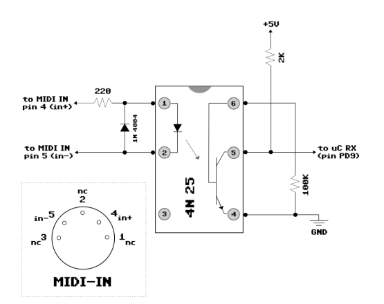
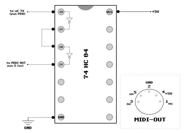
(note) I'd suggest to put both MIDI in and out circuits on one tripad board. the ground/+5V connections can then be shared.
(note) use electrical tape to isolate the board once everything's working
connecting the LCD module:
GPIO to HDD44780 pin mapping:
PE_7 -> P13(DB6) PE_8 -> P14(DB7)
PE_9 -> P11(DB4) PE10 -> P12(DB5)
PE11 -> P_5(R/W) PE12 -> P_6(E)
PE13 -> P_4(RS) PE14 -> 2N 3904 Base (PWM Dimmer)
(note) simply tie LCD pin 3 (VO, operating voltage) to ground
(hopefully you did not get an LCD that requires a negative voltage!)
(note) as you can see, the 4-bit LCD interface mode is used
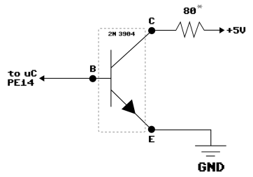
connecting the LCD pulse-width backlight modulator (dimmer):
(click on an image to see the full-size version)
|
This circuit is pretty simple.
GPIO PE14 drives the transistor at a pulse-signal frequency of 80 KHz.
The length of the pulse duty cycle controls the LCD brightness (256 levels).
(note) the actual value of the resistor* depends on the backlight voltage level and power consumption.
Mine (a Displaytech white-on-blue) requires a supply voltage of 3.4V and consumes 20mA.
Inserted into the U = R * I formula gives:
(5V - 3.4V) = 1.6V = R * 0.020A = 1.6V/0.020A = R = 80 Ohm
i.e. a CrystalFontz display which requires 4.2V and consumes 210mA would require
a (5V - 4.2V) = 0.8V = R * 0.210A = 0.8V/0.210A = 3.8 Ohm resistor.
(note) maybe an additional resistor should be added between PE14 and
the transistor base but it works fine without one.
|  |
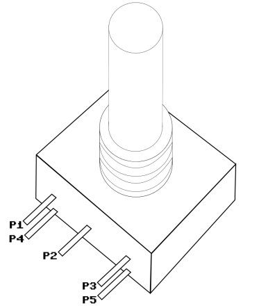
connecting the rotary encoders:
(click on an image to see the full-size version)
|
- Pin 1 (phase B) is connected to PC6 (Enc#1)
PC8 (Enc#2)
PB5 (Enc#3)
PC10 (Enc#4)
- Pin 2 (ground) is connected to pin 4
(note) why did not they build this connection
into the rotary encoder ?!
- Pin 3 (phase A) is connected to PC7 (Enc#1)
PC9 (Enc#2)
PB4 (Enc#3)
PC11 (Enc#4)
- Pin 4 is connected to ground (and to pin 2)
- Pin 5 (pushbutton) is connected to PD0 (Enc#1)
PC12 (Enc#2)
PD2 (Enc#3)
PD1 (Enc#4)
(note) according to the encoder datasheet, ~8K ohm resistors
need to be inserted between phase A/B and the GPIO pin.
I am not sure if they are really required. However, when
I built my box, I included them.
(note) you may be tempted to connect enc#3 phase A/B to PA9/8
but for some reason this won't work (reliably).
(note) pull up resistors for the pushbuttons are not required since
the STM32F4 already has them on board.
(note) when mounting the rotary encoders, the pins point _away_ from the LCD.
|
|
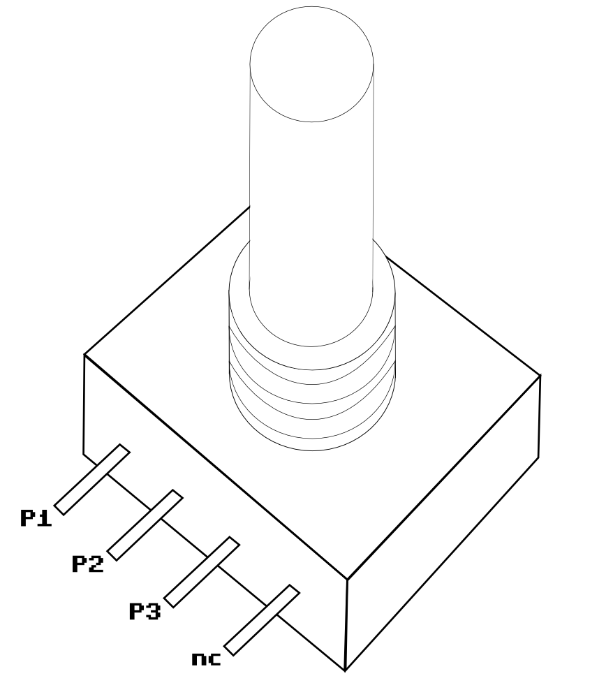
connecting the potentiometers:
(click on an image to see the full-size version)
|
- Pin 1 is connected to +3V
- Pin 2 is connected to PA1 (Pot#1)
PA0 (Pot#2)
PA3 (Pot#3)
PA2 (Pot#4)
- Pin 3 is connected to ground
(note) I tried adding a 22nF..100nF ceramic condensator
between pin3 and GND as an anti-jitter
measurement but you can leave it out since
it did not really improve much.
(the 100nF condensator added a considerable
lag to pot movements)
(note) the resistance between pins 1 and 3 is ~10K Ohm
(note) when mounting the pots, the pins point towards the LCD.
you may need to (gently) bend the pot pins by 90°.
(note) jitter-protection is done in software (micro movement timeouts and
by taking n+2*m samples, sorting them, discarding the lowest
and highest 'm' samples, then averaging 'n' samples)
|

|
connecting the pushbuttons:
I am not going to draw a picture for this :-)
Just connect one pin to the GPIO pin and the other one to ground.
Here's the pushbutton to GPIO mapping:
Button #1: PB9
Button #2: PD3
Button #3: PD6
Button #4: PD5
(note) you may be tempted to connect button #1 to PD4 but this won't work since it is also the reset pin of the CS43L22 (audio DAC)
(note) the board has built-in pull-up resistors
(note) button debouncing is done in software
connecting the audio line-out:
The STM32F4 board already has a line-out connector.
You could make a hole into the case and squeeze a plug through it but I decided to get an angled plug and solder another connector to it
(i.e. just some kind of extension cord and strain relief).
Take a look at the datasheet of your connector to see which pin connects to what.
In general, the tip of the audio plug carries the left channel, the area behind the first ring the right channel, and the rest
needs to be connected to ground.
[cost]
the hardware costs approximately 60..90 euros, depending on the quality of the parts and what you already have in stock (wire, ..).
it takes about 2-3 days to build one unit.
[downloads]
the latest firmware can be downloaded here:
midibox-v016.hex [07-Oct-2012].
[contact]
if you have any questions or advice, drop me a mail: bs AT tkscript DOT de.
 (true to scale PDF)
- LCD: recess ("aussparung") for the visible area of the LCD module.
(note) it is very important that the module fits in tightly, otherwise the backlight will shine through!
- R1..R4: drill holes for the rotary encoders. approximately 6mm in diameter.
the distance of the R1/R4 center to the left/top resp. right/top case corner is (~25mm; ~25mm).
- P1..P4: drill holes for the potentiometers. approximately 7mm in diameter.
the distance of the P1/P4 center to the left/bottom resp. right/bottom case corner is (~25mm; ~23mm).
(note) do not place them any higher than this or they will collide with the LCD module!
- B1..B4: drill holes for the pushbuttons. approximately 6mm in diameter.
the distance of the B1/B2 center to the left/top resp. right/top case corner is (~11mm; ~40mm).
the distance of the B4/B3 center to the left/bottom resp. right/bottom case corner is (~11mm; ~33mm).
- MIDI in/out: (top-side) drill holes for the MIDI ports. approximately 16mm in diameter.
the distance of the in/out connector center to the left/right corners of the case is ~28mm.
- USB: (left-side) drill hole for the mini-B USB plug. size is (~6mm; ~10mm) (plug is rotated 90°).
the distance of the top edge of the USB connector to the bottom edge of the case is ~60mm.
- Audio: (right-side) drill hole for the 3.5mm stereo line out connector. approximately 6mm in diameter.
the vertical distance of the drill hole center to the right/bottom case corner is ~27mm.
(note) the connector I used was not long enough for the counter-nut to fit so I had to file/abrade
the case on the inside to make it fit
Here's how I prepared the case:
1) Cut away all the separators/bars (if that's the right term) on the inside of the case front so the surface becomes flat
2) Measure the exact size of the LC display area (it's ~94.4x30.6mm but this may vary by up to 3mm, especially the width)
then use the ruler and pencil and draw an outline on the front side of the case.
3) Attach the diamond disc to the dremel and roughly cut out the LCD area at medium rotational speed
(note) do not cut too close to the outline markers!
(note) if you do not have a dremel, use the power drill and make a lot of holes.. then use a side cutter (and/or tinsnips if available)
4) Use the flat file (and the ruler to make sure everything's even) until the LCD tightly fits through the hole
(note) this may take an hour or two. be patient and precise!
5) Again use the ruler and pencil and mark the centers of the rotary/pot/pushbutton drill holes
6) Use a small drill to prepare the drill holes.
(note) the wood drill bits have a sharp tip which you can place in the prepared holes so that the drill does not slip and slide
7) Use the wood drill bits to cut out the actual holes. Use the round file to clean up the holes ("entgraeten").
8) Repeat 6) and 7) for the MIDI and audio drill holes
9) Make a hole for the USB plug (pencil/ruler/small drill/flat file)
10) done!
ground/+5V/+3V connections (general):
I used three stripboards to group the power/ground connections.
general tips:
- when soldering wire to a pin, you may find that putting some solder on the wire first makes things a bit easier ("verzinnen").
- grouping wires and fixating them with another short piece of wire (tied around the wire bundle, then tightened with pliers)
makes it easier to trace/debug individual wires later on (in the end, there are a _lot_ of wires in that relatively small box)
You should also add a label to each wire group (I use small pieces of paper placed on adhesive tape).
- it may be a good idea to use shrink-on tubes ("schrumpfschlauch") for the wire/pin connections
the MIDI in/out board:
(click on an image to see the full-size version)
(true to scale PDF)
- LCD: recess ("aussparung") for the visible area of the LCD module.
(note) it is very important that the module fits in tightly, otherwise the backlight will shine through!
- R1..R4: drill holes for the rotary encoders. approximately 6mm in diameter.
the distance of the R1/R4 center to the left/top resp. right/top case corner is (~25mm; ~25mm).
- P1..P4: drill holes for the potentiometers. approximately 7mm in diameter.
the distance of the P1/P4 center to the left/bottom resp. right/bottom case corner is (~25mm; ~23mm).
(note) do not place them any higher than this or they will collide with the LCD module!
- B1..B4: drill holes for the pushbuttons. approximately 6mm in diameter.
the distance of the B1/B2 center to the left/top resp. right/top case corner is (~11mm; ~40mm).
the distance of the B4/B3 center to the left/bottom resp. right/bottom case corner is (~11mm; ~33mm).
- MIDI in/out: (top-side) drill holes for the MIDI ports. approximately 16mm in diameter.
the distance of the in/out connector center to the left/right corners of the case is ~28mm.
- USB: (left-side) drill hole for the mini-B USB plug. size is (~6mm; ~10mm) (plug is rotated 90°).
the distance of the top edge of the USB connector to the bottom edge of the case is ~60mm.
- Audio: (right-side) drill hole for the 3.5mm stereo line out connector. approximately 6mm in diameter.
the vertical distance of the drill hole center to the right/bottom case corner is ~27mm.
(note) the connector I used was not long enough for the counter-nut to fit so I had to file/abrade
the case on the inside to make it fit
Here's how I prepared the case:
1) Cut away all the separators/bars (if that's the right term) on the inside of the case front so the surface becomes flat
2) Measure the exact size of the LC display area (it's ~94.4x30.6mm but this may vary by up to 3mm, especially the width)
then use the ruler and pencil and draw an outline on the front side of the case.
3) Attach the diamond disc to the dremel and roughly cut out the LCD area at medium rotational speed
(note) do not cut too close to the outline markers!
(note) if you do not have a dremel, use the power drill and make a lot of holes.. then use a side cutter (and/or tinsnips if available)
4) Use the flat file (and the ruler to make sure everything's even) until the LCD tightly fits through the hole
(note) this may take an hour or two. be patient and precise!
5) Again use the ruler and pencil and mark the centers of the rotary/pot/pushbutton drill holes
6) Use a small drill to prepare the drill holes.
(note) the wood drill bits have a sharp tip which you can place in the prepared holes so that the drill does not slip and slide
7) Use the wood drill bits to cut out the actual holes. Use the round file to clean up the holes ("entgraeten").
8) Repeat 6) and 7) for the MIDI and audio drill holes
9) Make a hole for the USB plug (pencil/ruler/small drill/flat file)
10) done!
ground/+5V/+3V connections (general):
I used three stripboards to group the power/ground connections.
general tips:
- when soldering wire to a pin, you may find that putting some solder on the wire first makes things a bit easier ("verzinnen").
- grouping wires and fixating them with another short piece of wire (tied around the wire bundle, then tightened with pliers)
makes it easier to trace/debug individual wires later on (in the end, there are a _lot_ of wires in that relatively small box)
You should also add a label to each wire group (I use small pieces of paper placed on adhesive tape).
- it may be a good idea to use shrink-on tubes ("schrumpfschlauch") for the wire/pin connections
the MIDI in/out board:
(click on an image to see the full-size version)

 (note) I'd suggest to put both MIDI in and out circuits on one tripad board. the ground/+5V connections can then be shared.
(note) use electrical tape to isolate the board once everything's working
connecting the LCD module:
GPIO to HDD44780 pin mapping:
PE_7 -> P13(DB6) PE_8 -> P14(DB7)
PE_9 -> P11(DB4) PE10 -> P12(DB5)
PE11 -> P_5(R/W) PE12 -> P_6(E)
PE13 -> P_4(RS) PE14 -> 2N 3904 Base (PWM Dimmer)
(note) simply tie LCD pin 3 (VO, operating voltage) to ground
(hopefully you did not get an LCD that requires a negative voltage!)
(note) as you can see, the 4-bit LCD interface mode is used
connecting the LCD pulse-width backlight modulator (dimmer):
(click on an image to see the full-size version)
(note) I'd suggest to put both MIDI in and out circuits on one tripad board. the ground/+5V connections can then be shared.
(note) use electrical tape to isolate the board once everything's working
connecting the LCD module:
GPIO to HDD44780 pin mapping:
PE_7 -> P13(DB6) PE_8 -> P14(DB7)
PE_9 -> P11(DB4) PE10 -> P12(DB5)
PE11 -> P_5(R/W) PE12 -> P_6(E)
PE13 -> P_4(RS) PE14 -> 2N 3904 Base (PWM Dimmer)
(note) simply tie LCD pin 3 (VO, operating voltage) to ground
(hopefully you did not get an LCD that requires a negative voltage!)
(note) as you can see, the 4-bit LCD interface mode is used
connecting the LCD pulse-width backlight modulator (dimmer):
(click on an image to see the full-size version)